Overview
Current-limiting fuses reduce both the magnitude and duration of a fault current.
Using Current-Limiting Fuses
A UL Listed, current-limiting fuse must clear a short circuit current in less than one half cycle. In its current-limiting range, the fuse will melt in the first quarter cycle and prevent the fault current from reaching the first peak of the asymmetrical waveform, tremendously limiting the total electrical energy delivered to the fault.
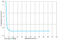
Incident energy chart of 400A Class J fuse.
This energy limitation enables class J, RK1, T and L fuses to reduce incident heat energy from an arc flash to very low levels. The incident energy performance curve of a 400 amp, Class J fuse shows that, for defined parameters, the predicted incident energy would be 0.3 cal/cm². Compare this to 9.2 cal/cm², the result for an overcurrent protective device clearing in six cycles. (Comparison made using IEEE 1584 fuse equations and standard equations for the cycle device).
IEEE 1584 Equations Apply to Mersen Fuses
IEEE 1584 offers standard equations to predict incident energy and arc flash boundary distances for Class RK1 and Class L fuses up to 2,000 ampres.
Extensive testing at our high-power lab, in accordance with IEEE 1584 test procedures, has shown that Mersen's Amp-Trap 2000® A6D (Class RK1) and A4BQ (Class L) fuses yield incident energy levels at or below those predicted by the IEEE 1584 fuse equations. Our Amp-Trap 2000® AJT (Class J) fuse exceeds the performance of these equations for the equivalent ampere rating.
Show lessUnderstanding Current Limitation
Current limitation is one of the most important features of today's fuses. By isolating a faulted circuit before the fault current has sufficient time to reach its maximum value, a current-limiting fuse can:
- Limit the total energy delivered to arcing faults.
- Limit thermal and mechanical stresses created by the fault currents.
- Reduce the magnitude and duration of the system voltage drop caused by fault currents.
- Minimize downtime, since current-limiting fuses can be precisely and easily coordinated even under short circuit conditions.
The degree of current limitation provided by a fuse is measured two ways — peak let-thru current (lp) and I²t. Maximum allowable lp and I²t values are specified in UL standards for all UL Listed current-limiting fuses, and are available on all semiconductor fuses.
Short circuit currents usually have a decaying asymmetrical wave shape in the first several cycles of the fault, as illustrated in Figure 1. The first peak is the highest; in theory, the peak available fault current can be anywhere from 1.414 to 2.828 times the RMS available in a circuit where the impedance is all reactance with no resistance. In reality, all circuits include some resistance, and the 2.3 multiplier has been chosen as a practical limit.
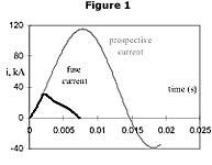
Figure 1: Short circuit currents usually have a decaying asymmetrical wave shape in the first several cycles of the fault.
Let-Thru Current
Let-thru current is the current passed by a fuse while the fuse is interrupting a fault that is within its current-limiting range.
As the fault current begins to rise in the first half cycle, the element in the current-limiting fuse melts. The added impedance created by the resultant arc causes the current to max out and begin to decrease.
The highest instantaneous value reached is referred to as peak let-thru current, and is expressed as a peak instantaneous value (lp).
Ip is useful in predicting peak electromagnetic forces created throughout the faulted circuit. The peak forces will be proportional to the square of the instantaneous value of current of the first half-cycle peak, or Ip2, for current-limiting fuses.
Ip versus I²t
When it comes to predicting the energy delivered to a fault, Ip has rather limited usefulness. Two fuses can have the same Ip, but different total clearing times, as shown in Figure 2.
The fuse that clears in time "A" will provide better component protection than the fuse that clears in time "B." Fuse clearing I²t takes into account Ip and total clearing time. Fuse clearing I²t values are derived from oscillograms of fuses tested within their current-limiting range and are calculated as follows:
I²t = ∫tI²dt
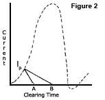
Figure 2: Two fuses can have the same Ip, but different total clearing times.
The "t" in the equation is the total clearing time for the fuse. Although I²t is actually (IRMS)²t, it is generally understood that the "I" in I²t is really IRMS, and the RMS is dropped for the sake of brevity.
In Figure 2, note that since clearing time "B" is approximately twice clearing time "A," the resultant I²t for that fuse is greater than the I²t for the fuse with clearing time "A," and its level of protection is correspondingly lower.
The I²t passed by a fuse depends on the fuse characteristics and applied voltage. As application voltage decreases, I²t will decrease. Unless stated otherwise, published I²t values are based on AC testing. The I²t passed by a fuse in a DC application may be higher or lower based on the voltage, available fault current and time constant of the DC circuit.
Fuse I²t value can be used to determine the level of protection provided to circuit components under fault current conditions. I²t is proportional to the energy delivered to the faulted circuit (I²Rt). I²t for a specific fuse design will be lower for higher fault currents until the fuse reaches adiabatic melting.
Manufacturers of diodes, thyristors, triacs and cable publish I²t withstand ratings for their products. To protect one of these devices, a fuse should have a clearing I²t that is lower than the withstand I²t of the device.
Show lessPeak Let-Thru Charts and Tables
Using Peak Let-Thru Charts
Ip data is generally presented in the form of a graph. The X axis [1] is available fault current in RMS symmetrical amps and the Y axis [2] is instantaneous peak let-thru current in amps.
Peak let-thru chart for A6D200R fuse.
The line labeled "maximum peak current circuit can produce" [3] gives the worst-case peak current possible with no fuse in the circuit. The fuse characteristic line [4] is a plot of the peak let-thru currents passed by a given fuse at various available fault currents.
In the peak let-thru graph above, assume that an A6D200R fuse is to be applied where the available fault current is 40,000 amperes RMS. The graph shows that the maximum peak available current with no fuse in the circuit is 92,000 amperes (40,000 x 2.3). The A6D200R fuse will limit the peak let-thru current to only 14,000 amperes.
Using Peak Let-Thru Tables
Although the characteristics of current-limiting fuses are represented in peak let-thru charts, peak let-thru tables are easier to use.
Based on peak let-thru charts, the tables reflect fuse tests at 15% power factor at rated voltage, with prospective fault currents as high as 200,000 amperes. At each prospective fault current, let-thru data is given in two forms—IRMS and Ip.
Where IRMS is the apparent RMS symmetrical current and Ip is the maximum peak instantaneous current passed by the fuse, the lp let-thru current is 2.3 times IRMS. This relationship exists between peak current and RMS available current under worst-case test conditions (i.e., closing angle of 0° at 15% power factor).
Using let-thru tables saves time and reduces the possibility of errors. The tables are also helpful when comparing the current-limiting capability of various fuses.
Click on the fuse name to view its peak let-thru table:
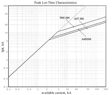
Let-Thru Comparison
The chart below compares the peak let-thru current for Class RK5 (TRS 200), Class RK1 (AGD 200) and Class J (AJT 200) fuses.
Recommended Fuses for Reducing Arc Flash Energy
Typically, the fuses we recommend for arc flash energy reduction are UL Listed branch circuit fuses with the highest degree of current limitation. The fuses shown here have had excellent results in laboratory tests, limiting arc flash incident energies to very low values for arc fault currents within their current-limiting range.
Amp-Trap 2000® A4BQ Class L Fuse
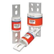
Designed for applications greater than 600 amperes, A4BQ offers an interrupting rating of 300 kA and a unique design that delivers excellent performance in arc flash situations.
View Details
Amp-Trap 2000® AJT Class J Fuse
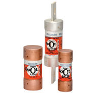
The ideal choice for new applications of 600 amperes and less, AJT offers excellent current-limiting performance for short circuits and time delay for overloads. The unique Class J dimensions prevent improper substitutions.
View Details
Amp-Trap 2000® A6D Class RK1 Fuse
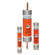
The ideal choice for upgrading existing applications of 600 amperes and less, the A6D offers excellent current-limiting performance for short circuits and time delay for overloads. Its dimensions allow for simple upgrades of existing Class H, Class K and Class RK5 fuses.
View Details
To see how well these fuses limit incident energy, use our calculator. To discuss how Mersen fuses can help reduce arc flash hazards in your facility, email us or call our Technical Services department.
Show lessHelpful Examples
Replace fuses with UL Class RK1 fuses to lower incident energy.
Arc flash incident energies can often be significantly reduced by simply replacing UL Class RK5, Class K, and Class H fuses with A6D UL Class RK1 fuses. This is an easy and inexpensive solution, since the A6D fuses fits into the same fuse holders. Upgrading to A6D Class RK1 fuses can reduce arc flash energies because these fuses have lower let-through energies in their current limiting range and lower current limiting thresholds. Please note that Class H fuses are not current limiting and have a very low interrupting rating. If there are any of these left in your system you should plan to retire these as soon as safely possible.
- Download Tech Topic
Reduce Ampere Ratings to lower incident energy.
If the arcing fault current is less than the fuse’s threshold current, the fuse will limit t but not Irms and the incident energy will be higher. The value will depend on the clearing time of the fuse. Within the same fuse class, current-limiting fuses that have lower ampere ratings will have lower threshold currents. This wider range of current-limiting operation can be used to reduce arc flash energy in applications where available fault currents are low relative to the existing fuse’s threshold value.
- Download Tech Topic
Reducing LV Switchgear incident energy to below Extreme Hazard
Arc flash incident energy calculations are frequently above 40 cal/cm2 for equipment connected directly to the secondary side of power transformers due to existing electrical system designs and transformer fuse protection practices. Many companies use this value as the upper limit for energized work. Consequently these companies must now insist on outages to perform routine tasks on this equipment. When the equipment is switchgear feeding large processes, the downtime cost of a task such as racking in and closing a power circuit breaker can be tens of thousands of dollars In some cases, it is possible to reduce energies below 20 cal/cm2 and maintain reliable operation by using a fuse with different time current characteristics.
- Download Tech Topic
Show less