Overview
In Mersen's high-power test lab in Newburyport, Massachusetts, our engineers study the effects of arc fault and arc flash phenomena. They utilize this data in the development of innovative circuit protection devices and share it with regulatory bodies and other industry groups to help improve worker safety.
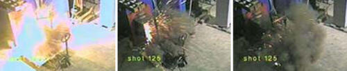
These photo sequences, taken from video of actual tests, give you an idea of the energy released during these types of events.
Test Sequence 1
Test Sequence 1: Arcing Fault
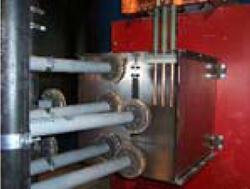
Test is based on IEEE 1584 setup for "in the box" testing.
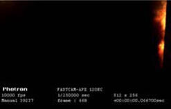
An arc flash occurs so quickly and generates such a blinding light, the human eye sees little but the aftermath. This sequence of photos, taken from high-speed, specially filtered digital video shot during testing at Ferraz Shawmut's high-power lab, illustrates the development of an arc flash and the hazards it generates.
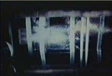
Based on the IEEE Standard 1584 setup for "in the box" testing, the test uses a 20" x 20" x 20" steel box (photo 1). Three-phase power is supplied through the top of the box via three ¾" copper electrodes spaced 1¼" apart. The tips of the electrodes are 10" from the top and 4" from the back of the box. The seven disks mounted on the horizontal poles are calorimeters used to measure heat.*
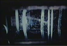
An arcing fault usually begins with an inadvertent connection between a phase conductor and ground or between two phases. In this test sequence, a wire connects all three phases, or electrodes (photo 2). The test lab is configured to deliver 23kA RMS to a bolted fault at the tips of the electrodes. When the conductors are energized, the wire vaporizes and initiates an arcing fault.
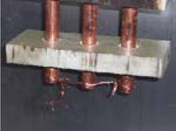
To initiate an arcing fault, a wire connects all three phases.
Although all of the events shown here occur in 100 milliseconds, the heat, light and thermoacoustic energy created during an arc flash is more than the human body can survive.
Analyses of power systems indicate that heat densities from arcing faults can range from 0.3 cal/cm² to over 100 cal/cm², depending on the electrical system values, equipment design and protective equipment in place. In this test, heat energy densities in excess of 6.8 cal/cm² were measured at typical working distances (18").
* For the video frames show, the calorimeters were moved to 4' to improve visibility. Measurements cited at 18" were from a similar test.
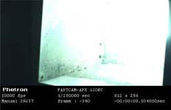
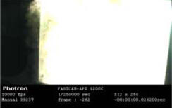
Photo 1: Time = 0.000 Seconds
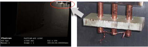
The test begins by closing the test lab's circuit breaker on the short circuit, indicated by the arrow in the photo above.
- Available fault current is 23kA
- Clearing time of circuit breaker is set at 6 cycles (0.1 seconds)
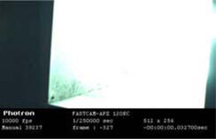
Photo 2: Time = 0.0002 Seconds
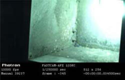
- Massive quantity of power is delivered to the conductor
- Rapid heating quickly takes the copper wire past its melting and boiling points
- As the circuit through the shorting conductor is broken, an arc is established between the electrodes
- Brilliant light begins to emanate from the arc
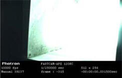
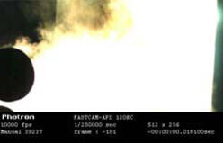
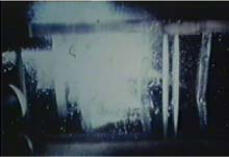
Photo 3: Time = 0.0007 Seconds
- Current flowing through highly ionized air converts electrical energy into massive amounts of heat energy, causing plasma cloud to expand outward, away from the electrodes
- Massive quantity—megawatts—of power delivered to the arc begins to increase
- Surrounding air undergoes ultra-rapid heating, but cannot expand fast enough to accommodate the extreme increase in heat energy; pressure begins to build
- Arc burns in a mixture of air and copper vapor from the electrodes
- Temperature of conducting plasma exceeds 10,000°C; at this temperature, air remains conductive
- Plasma jets begin to form, driven by increasing magnetic forces
- Light brilliance is well above eye-damaging levels
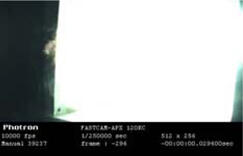
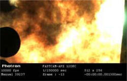
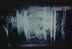
Photo 4: Time = 0.002 Seconds
- Current continues to flow through the plasma cloud, converting additional electrical energy into massive amounts of heat energy
- Plasma is initially forced downward from the electrodes by magnetic forces and the plasma jets
- Expansion of the heated air and vaporized copper, which is 67,000 times its solid volume, accelerates away from the arc at speeds nearing the speed of sound
- Molten metal from the electrodes is ejected into the plasma jets at the electrode tips
Photo 5: Time = 0.0032 Seconds
- Sustained current flow through plasma continues to convert electrical energy into massive amounts of heat energy
- With continued heating, plasma continues to expand away from the arc to the front of the test box, and is driven downward from electrodes by the plasma jets
- Molten metal from electrodes continues to be ejected into plasma jets
- Light brilliance still well above eye-damaging levels
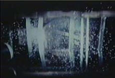
Photo 6: Time = 0.0051 Seconds
- Sustained current flow through the plasma continues to convert electrical energy into massive amounts of heat energy
- Plasma is initially forced downward from the electrodes by the growing plasma jets
- Continued heating of plasma causes it to expand beyond the test box
- Both sides of the box are visibly distended by the increasing pressure
- Molten metal from the electrodes continues to be ejected at high velocity into the plasma jets; some will exit the box with the explosive expansion of air
- Light brilliance still well above eye-damaging levels
Photo 7: Time = 0.0085 Seconds
- First half-cycle of fault is complete
- Sustained current flow through plasma cloud continues to convert electrical energy into massive amounts of heat energy
- Plasma has expanded beyond test box
- More molten metal from electrodes is being ejected into the plasma jets
- Light brilliance still well above eye-damaging levels
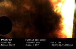
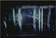
Photo 8: Time = 0.0167 Seconds
- First electrical cycle is complete
- Cooling copper ions combine with oxygen to form copper oxide "dust," which appears as brownish smoke; other toxic gases are formed in similar fashion
- Calorimeter at 4' becomes visible from expanding plasma cloud
- Sustained current flow continues to convert electrical energy into massive amounts of heat energy
- More molten metal is being ejected into plasma jets
- Shrapnel from the explosive force of the arc is hurled outward at high velocity
- Light brilliance still well above eye-damaging levels
Photo 9: Time = 0.0334 Seconds
- Second electrical cycle is complete
- Sustained current flow through plasma continues to convert electric energy to heat energy
- Plasma still beyond test box
- More copper oxide dust and other toxic gases are visible
- More molten metal is being ejected into plasma jets
- Light brilliance still above eye-damaging levels
Photo 10: Time = 0.0504 Seconds
- Third electrical cycle is complete
- Sustained current flow through plasma continues to convert electrical energy to massive amounts of heat energy
- Copper oxide dust and other toxic gases obscuring view of calorimeter and box interior
- Plasma in test box still visible
- More molten metal being ejected into plasma jets
- Light brilliance still above eye-damaging levels
Photo 11: Time = 0.1015 Seconds
- Test lab circuit breaker opens
- Interruption of current flow stops conversion of electrical energy to heat energy; plasma begins to cool
- Remaining toxic gases are forced outward
- Remaining molten metal being ejected into plasma jets
Photo 12: Final Observations and Measurements
- Amount of heat energy accumulated at front of box exceeded 6 cal/cm². Heat incident on measuring devices at 18" working distance indicated heat levels capable of causing third-degree burns on exposed flesh and igniting conventional clothing
- Impulse sound levels were above OSHA's 140 dB limit. Without protection, permanent hearing impairment would be expected
- Light levels were intense enough to cause immediate vision impairmentand increased chance of future cataract development
- Toxic gases, such as copper oxide dust, were forced out of enclosure
- Shrapnel was ejected at high velocities
- Molten metal projectiles contained enough heat to ignite conventional clothing
Test sequence 2
Test Sequence 2: Exceeding the Short Circuit Rating of Equipment
When short circuit currents surpass equipment's short circuit rating, electromagnetic forces can seriously damage the equipment and initiate an arc fault. This test sequence shows what can happen when a short circuit rating downstream of the equipment exceeds its short circuit rating.
The images illustrate how current flowing in opposite directions through parallel bus bars can create a repulsive force between them, causing them to distort or even break away. When the bus bars contact other conductors or grounded components, an explosive arc fault is initiated.
Photo 1
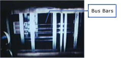
The test lab circuit breaker is closed on the bolted fault downstream of the equipment. (Steel panels have been removed to show the underlying steel structure and bus bars.)
Photo 2
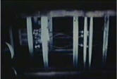
- Current flows away from the source in the bottom bus bar and returns in the top two bars.
- Current is flowing in opposite directions in the middle and bottom bus bars; the resultant electromagnetic force repels the middle bus bar away from the bottom bus bar
- Force increases to its peak as the AC current rises to its first peak value
Photo 3
- Contact between the conductors is made
- Resultant high-energy arcs create an explosion, displacing top bar from its supports
- Molten metal begins to be expelled
Photo 4
- Displaced bus bar continues to move, approaching the grounded steel structure
- Initial arcs have self-extinguished
Photo 5

- Contact is made between displaced bus bar and grounded steel structure
- Brilliant flash of light occurs
- Arc plasma and explosive forces are created
Photo 6
- Light brilliance has decayed further
- Arc continues to supply heat to plasma around it
- Molten metal has been ejected farther from structure
Photo 7
- Arc has extinguished
- Volume of molten metal being expelled clearly visible; non-molten particles not visible, due to camera filter used
Photo 8
- Molten shrapnel has moved farther from structure
Photo 9
- Event is nearly complete
- Last of visible shrapnel appears